Digital IC Design - Streaming Control
In digital IC design, data flows through pipelines of processing stages connected by FIFOs and buffers. A fundamental challenge is ensuring that downstream buffers don’t overflow while maintaining maximum throughput. Two primary flow control mechanisms address this challenge: backpressure and credit. This post explores both mechanisms in detail, including practical implementations and design guidance.
Pipeline Abstract Model
The typical abstraction model for chip circuit design follows a pattern of FIFO/Buffer → Pipeline → FIFO/Buffer → Pipeline, as illustrated conceptually:
1
2
3
4
┌──────┐    ┌────────┐    ┌──────┐    ┌────────┐    ┌──────┐
│Stage │───▶│ FIFO/  │───▶│Stage │───▶│ FIFO/  │───▶│Stage │
│  A   │    │ Buffer │    │  B   │    │ Buffer │    │  C   │
└──────┘    └────────┘    └──────┘    └────────┘    └──────┘
This raises a critical question: How do we prevent downstream buffer overflow while maintaining line-rate performance?
The two dominant approaches are backpressure (BP) and credit-based flow control, each with distinct trade-offs in complexity, buffer requirements, and robustness.
Backpressure Mechanism
Principle
In the backpressure mechanism, the receiver actively signals its buffer status to the sender. When the receiver’s buffer is nearing capacity, it asserts a backpressure signal to instruct the sender to stop transmitting new data.
Workflow
- Receiver monitors its own buffer usage continuously
- When buffer usage reaches a threshold (high watermark), the receiver asserts a backpressure signal
- Sender receives the backpressure signal and stops sending new data
- When buffer usage drops below a threshold (low watermark), the receiver de-asserts backpressure
- Sender resumes data transmission
Implementation Example
Here’s a practical SystemVerilog implementation of the backpressure mechanism:
1
2
3
4
5
6
7
8
9
10
11
12
13
14
15
16
17
18
19
20
21
22
23
24
25
26
27
28
29
30
31
32
33
34
35
36
37
38
39
40
41
42
43
44
45
46
47
48
49
50
51
52
53
54
55
56
57
58
59
60
61
62
63
64
65
66
67
68
69
70
71
72
73
74
75
76
77
78
79
80
81
82
83
84
85
86
87
88
89
90
91
92
93
94
95
96
97
98
99
100
101
// Receiver module with backpressure generation
module receiver_with_backpressure #(
    parameter DATA_WIDTH = 32,
    parameter BUFFER_DEPTH = 16,
    parameter HIGH_WATERMARK = 12,  // Assert BP when buffer has 12+ entries
    parameter LOW_WATERMARK = 4     // De-assert BP when buffer has <4 entries
)(
    input  logic                  clk,
    input  logic                  rst_n,

    // Upstream interface
    input  logic                  data_vld_i,
    input  logic [DATA_WIDTH-1:0] data_i,
    output logic                  backpressure_o,

    // Downstream interface (processing)
    output logic                  data_vld_o,
    output logic [DATA_WIDTH-1:0] data_o,
    input  logic                  data_rdy_i
);

    // FIFO storage
    logic [DATA_WIDTH-1:0] buffer [BUFFER_DEPTH-1:0];
    logic [$clog2(BUFFER_DEPTH):0] wr_ptr, rd_ptr;
    logic [$clog2(BUFFER_DEPTH):0] buffer_count;

    // Calculate buffer occupancy
    assign buffer_count = wr_ptr - rd_ptr;

    // Backpressure generation with hysteresis
    always_ff @(posedge clk or negedge rst_n) begin
        if (!rst_n) begin
            backpressure_o <= 1'b0;
        end
        else begin
            if (buffer_count >= HIGH_WATERMARK) begin
                backpressure_o <= 1'b1;  // Assert BP
            end
            else if (buffer_count < LOW_WATERMARK) begin
                backpressure_o <= 1'b0;  // De-assert BP
            end
            // Otherwise maintain current state (hysteresis)
        end
    end

    // Write to buffer when valid data arrives
    always_ff @(posedge clk or negedge rst_n) begin
        if (!rst_n) begin
            wr_ptr <= '0;
        end
        else if (data_vld_i && (buffer_count < BUFFER_DEPTH)) begin
            buffer[wr_ptr[$clog2(BUFFER_DEPTH)-1:0]] <= data_i;
            wr_ptr <= wr_ptr + 1'b1;
        end
    end

    // Read from buffer when downstream is ready
    always_ff @(posedge clk or negedge rst_n) begin
        if (!rst_n) begin
            rd_ptr <= '0;
            data_vld_o <= 1'b0;
        end
        else if (data_rdy_i || !data_vld_o) begin
            if (buffer_count > 0) begin
                data_o <= buffer[rd_ptr[$clog2(BUFFER_DEPTH)-1:0]];
                data_vld_o <= 1'b1;
                rd_ptr <= rd_ptr + 1'b1;
            end
            else begin
                data_vld_o <= 1'b0;
            end
        end
    end

endmodule


// Sender module responding to backpressure
module sender_with_backpressure #(
    parameter DATA_WIDTH = 32
)(
    input  logic                  clk,
    input  logic                  rst_n,

    // Data source
    input  logic                  src_data_vld_i,
    input  logic [DATA_WIDTH-1:0] src_data_i,
    output logic                  src_data_rdy_o,

    // Downstream interface with backpressure
    output logic                  data_vld_o,
    output logic [DATA_WIDTH-1:0] data_o,
    input  logic                  backpressure_i
);

    // Send data only when backpressure is not asserted
    assign data_vld_o = src_data_vld_i && !backpressure_i;
    assign data_o = src_data_i;
    assign src_data_rdy_o = !backpressure_i;

endmodule
Buffer Depth Considerations
As below figure shows, for line-rate performance, the buffer depth must account for the Round-Trip Time (RTT) - the time between when backpressure is asserted and when the sender stops transmitting:
- Headroom Space: Must cover the RTT overshoot - data that’s already in-flight when backpressure is asserted
- Working Space: Must cover the RTT for de-assertion - ensures no bubbles when resuming transmission
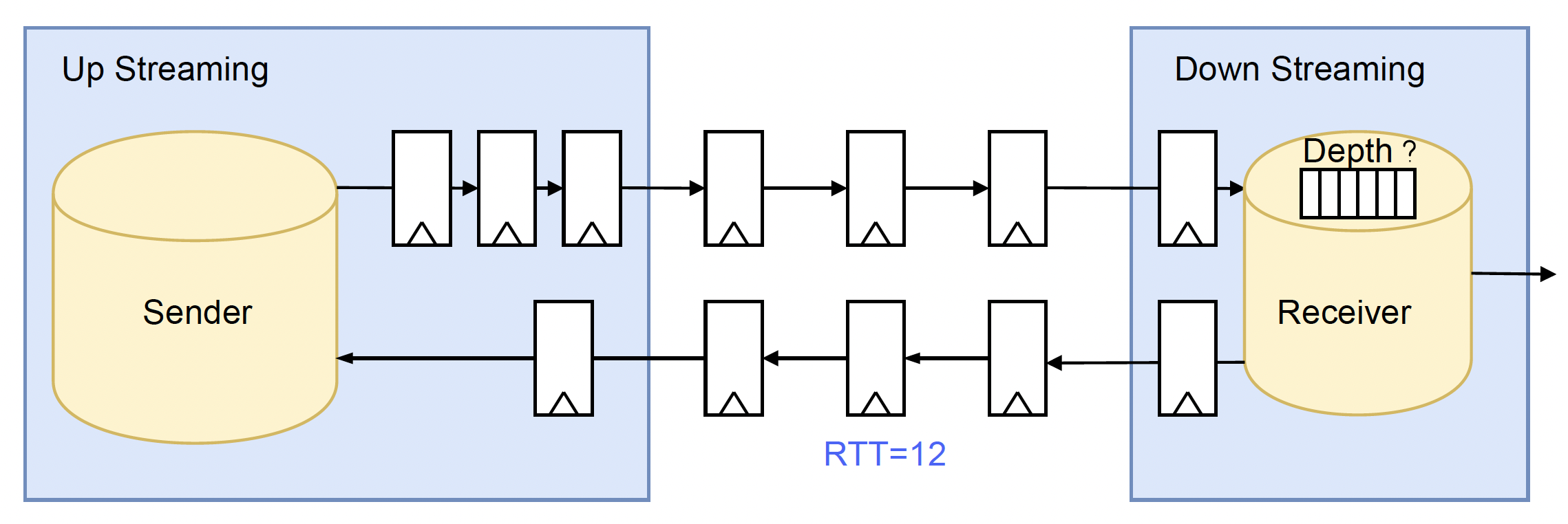
Rule of thumb: Buffer depth ≈ 2 × RTT × data_rate to maintain line-rate performance.
For example, if RTT = 4 cycles and the pipeline is full-throughput:
- Need 4 entries of headroom above high watermark
- Need 4 entries of working space below high watermark
- Total: ~8-16 entries depending on watermark settings
Advantages and Disadvantages
| Advantages | Disadvantages |
|---|---|
| Simple Design: Only requires threshold comparison logic - straightforward to implement and verify | Resource Cost: Larger buffers (requires ~2× RTT depth) mean more silicon area and power consumption |
| Robust: Tolerant to data loss or duplication in the pipeline - the receiver only cares about buffer fullness, not exact data counts |
Credit Mechanism
Principle
In the credit mechanism, the receiver pre-allocates a fixed number of “credits” to the sender. Each transmitted data unit consumes one credit. When credits are exhausted, the sender must stop. The receiver returns credits as it processes data from the buffer.
Workflow
- Initialization: Receiver allocates an initial credit count equal to its buffer capacity
- Send Operation: Sender transmits data and decrements its credit counter
- Credit Return: Receiver processes data from buffer and returns one credit to sender
- Flow Control: When sender’s credits reach zero, transmission pauses
- Resume: Sender resumes transmission upon receiving credits
Implementation Example
Here’s a practical SystemVerilog implementation of the credit mechanism:
1
2
3
4
5
6
7
8
9
10
11
12
13
14
15
16
17
18
19
20
21
22
23
24
25
26
27
28
29
30
31
32
33
34
35
36
37
38
39
40
41
42
43
44
45
46
47
48
49
50
51
52
53
54
55
56
57
58
59
60
61
62
63
64
65
66
67
68
69
70
71
72
73
74
75
76
77
78
79
80
81
82
83
84
85
86
87
88
89
90
91
92
93
94
95
96
97
98
99
100
101
102
103
104
105
106
107
108
109
110
111
112
113
114
115
// Receiver with credit return
module receiver_with_credit #(
    parameter DATA_WIDTH = 32,
    parameter BUFFER_DEPTH = 16,
    parameter CREDIT_WIDTH = $clog2(BUFFER_DEPTH+1)
)(
    input  logic                    clk,
    input  logic                    rst_n,

    // Upstream interface
    input  logic                    data_vld_i,
    input  logic [DATA_WIDTH-1:0]   data_i,
    output logic                    credit_return_vld_o,
    output logic [CREDIT_WIDTH-1:0] credit_return_o,

    // Downstream interface (processing)
    output logic                    data_vld_o,
    output logic [DATA_WIDTH-1:0]   data_o,
    input  logic                    data_rdy_i
);

    // FIFO storage
    logic [DATA_WIDTH-1:0] buffer [BUFFER_DEPTH-1:0];
    logic [$clog2(BUFFER_DEPTH):0] wr_ptr, rd_ptr;
    logic [$clog2(BUFFER_DEPTH):0] buffer_count;

    assign buffer_count = wr_ptr - rd_ptr;

    // Write to buffer
    always_ff @(posedge clk or negedge rst_n) begin
        if (!rst_n) begin
            wr_ptr <= '0;
        end
        else if (data_vld_i && (buffer_count < BUFFER_DEPTH)) begin
            buffer[wr_ptr[$clog2(BUFFER_DEPTH)-1:0]] <= data_i;
            wr_ptr <= wr_ptr + 1'b1;
        end
    end

    // Read from buffer and return credit
    always_ff @(posedge clk or negedge rst_n) begin
        if (!rst_n) begin
            rd_ptr <= '0;
            data_vld_o <= 1'b0;
            credit_return_vld_o <= 1'b0;
            credit_return_o <= '0;
        end
        else begin
            credit_return_vld_o <= 1'b0;  // Default

            if (data_rdy_i || !data_vld_o) begin
                if (buffer_count > 0) begin
                    data_o <= buffer[rd_ptr[$clog2(BUFFER_DEPTH)-1:0]];
                    data_vld_o <= 1'b1;
                    rd_ptr <= rd_ptr + 1'b1;

                    // Return one credit when data is read
                    credit_return_vld_o <= 1'b1;
                    credit_return_o <= 1'b1;
                end
                else begin
                    data_vld_o <= 1'b0;
                end
            end
        end
    end

endmodule


// Sender with credit tracking
module sender_with_credit #(
    parameter DATA_WIDTH = 32,
    parameter BUFFER_DEPTH = 16,
    parameter CREDIT_WIDTH = $clog2(BUFFER_DEPTH+1)
)(
    input  logic                    clk,
    input  logic                    rst_n,

    // Data source
    input  logic                    src_data_vld_i,
    input  logic [DATA_WIDTH-1:0]   src_data_i,
    output logic                    src_data_rdy_o,

    // Downstream interface with credits
    output logic                    data_vld_o,
    output logic [DATA_WIDTH-1:0]   data_o,
    input  logic                    credit_return_vld_i,
    input  logic [CREDIT_WIDTH-1:0] credit_return_i
);

    logic [CREDIT_WIDTH-1:0] credit_count;

    // Initialize with full buffer capacity worth of credits
    always_ff @(posedge clk or negedge rst_n) begin
        if (!rst_n) begin
            credit_count <= BUFFER_DEPTH;  // Initial credits
        end
        else begin
            // Update credit count based on sends and returns
            case ({data_vld_o, credit_return_vld_i})
                2'b01: credit_count <= credit_count + credit_return_i;  // Only return
                2'b10: credit_count <= credit_count - 1'b1;              // Only send
                2'b11: credit_count <= credit_count + credit_return_i - 1'b1;  // Both
                default: credit_count <= credit_count;                   // Neither
            endcase
        end
    end

    // Send data only when credits are available
    assign data_vld_o = src_data_vld_i && (credit_count > 0);
    assign data_o = src_data_i;
    assign src_data_rdy_o = (credit_count > 0);

endmodule
Buffer Depth Considerations
The credit mechanism is more buffer-efficient:
- No Overflow by Design: Credit count precisely matches buffer capacity: sender can never send more than the buffer can hold
- Line-Rate Operation: Only requires ~1× RTT depth since credits are returned immediately upon data consumption
Rule of thumb: Buffer depth ≈ 1 × RTT × data_rate for line-rate performance.
This represents approximately 50% buffer savings compared to backpressure.
Advantages and Disadvantages
| Advantages | Disadvantages |
|---|---|
| Buffer Efficiency: Requires roughly half the buffer depth of backpressure for equivalent performance | Design Complexity: Requires careful credit accounting on both sender and receiver sides |
| Precise Control: Exact tracking of available buffer space prevents wasted capacity | Reduced Robustness: Vulnerable to credit tracking errors (over-returning credits → buffer overflow; under-returning credits → performance degradation or starvation) |
| Error Recovery Challenges: Credit mismatches are difficult to detect and recover from | |
| Special Cases: Complex handling needed for data drops, duplications, or multi-path scenarios |
Note: Despite these challenges, the credit mechanism is widely used in modern chip designs and has proven to be effective and reliable when implemented correctly. The buffer savings often justify the additional complexity.
Conclusion
| Aspect | Backpressure | Credit |
|---|---|---|
| Design Complexity | Low - simple threshold logic | Higher - precise credit accounting |
| Buffer Requirements | ~2× RTT depth | ~1× RTT depth |
| Robustness | High - tolerates data anomalies | Lower - sensitive to credit errors |
| Best For | Simple pipelines, safety-critical designs | Buffer-constrained, high-performance systems |
| Implementation Time | Faster | Slower - more verification needed |
Both backpressure and credit mechanisms are proven flow control solutions in digital IC design. The choice between them depends on your specific constraints:
- Choose backpressure when simplicity, robustness, and faster development are priorities
- Choose credit when buffer resources are constrained and you can invest in careful implementation
There’s no universally “better” mechanism - the optimal choice depends on your design constraints, team expertise, and performance requirements.
Is this blog helpful? Help fuel more in-depth technical content by treating me to a coffee! Your support keeps the knowledge flowing ☕✨
