VLSI Design - SDC: Defining CLOCKs
The SDC (Synopsys Design Constraints) file is a text file that contains constraints for timing analysis. It instructs the timing analyzer how to analyze the design. A complete and correct SDC file is the foundation of successful timing closure. Among all constraints, clock definitions are the most essential and critical. This post introduces the most commonly used clock constraints: Base Clocks, Virtual Clocks, and Generated Clocks.
1. Base Clocks: The Foundation
Base clocks are the primary input clocks to your device. Unlike clocks derived internally (e.g., via a PLL), base clocks originate from off-chip oscillators or are forwarded from external devices.
The create_clock Command
The fundamental command for defining a base clock is create_clock. You can specify the period, name, waveform, and target port.
Scenario A: Standard System Clock
The most common requirement is defining a clock with a specific frequency on an input port.
1
2
# Defines a 100 MHz clock (10ns period) on port clk_sys
create_clock -period 10 -name clk_sys [get_ports clk_sys]
Note: The
-periodoption expects a time value, not a frequency. The default unit is typically nanoseconds (tool-dependent). A 100 MHz clock has a period of 10ns.
Scenario B: Phase Shifting & Duty Cycles
For source-synchronous interfaces (like DDR) or center-aligned data, you often need to define specific waveforms using the -waveform option.
1
2
3
# Creates a 100 MHz clock with a 90-degree phase shift.
# Waveform {rise_time fall_time}: rising edge at 2.5ns, falling edge at 7.5ns.
create_clock -period 10 -waveform {2.5 7.5} [get_ports clk_sys]
The -waveform option takes a list of edge times within one period, starting with the rising edge. By default (without -waveform), a clock rises at time 0 and falls at half the period.
Scenario C: Multiple Clocks on the Same Port
If your design supports multiple operating modes where a single port can be driven by different frequencies at different times, you must use the -add option to define multiple clocks on the same source.
1
2
3
create_clock -period 10 -name clk_primary [get_ports clk_sys]
# Use -add to prevent overwriting the first clock definition
create_clock -period 20 -name clk_low_power [get_ports clk_sys] -add
Important: Without the
-addoption, the secondcreate_clockcommand would overwrite the first. If these clocks never exist simultaneously, useset_clock_groups -physically_exclusiveto prevent false timing violations between them.
2. Virtual Clocks: Modeling the External World
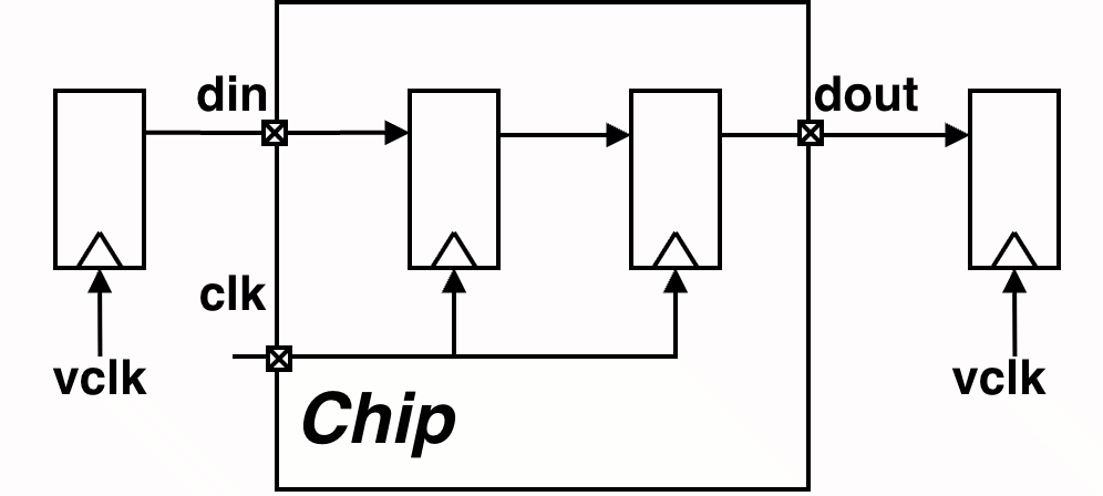
A Virtual Clock is a clock that exists conceptually but is not physically connected to any port or pin in the design. It is typically used to represent an external clock on the PCB that drives devices communicating with your chip but does not directly enter the chip itself.
Why Use Virtual Clocks?
- Accurate I/O Timing: Virtual clocks serve as the reference clock for
set_input_delayandset_output_delayconstraints when the external device operates on a different clock domain or when no physical clock port exists for the I/O interface. - Uncertainty Isolation: They allow you to apply different clock uncertainty values (jitter, skew) for external board-level timing versus the internal chip clock tree, providing more accurate timing analysis.
Implementation
To create a virtual clock, simply use create_clock without specifying a target port.
1
2
3
4
5
6
7
8
9
# 1. Create the internal base clock
create_clock -period 10 -name clk [get_ports clk]

# 2. Create a virtual clock representing the external device
create_clock -period 10 -name vclk

# 3. Constrain I/O using the VIRTUAL clock
set_input_delay -clock vclk 1.5 [get_ports din]
set_output_delay -clock vclk 1.5 [get_ports dout]
3. Generated Clocks: Managing Internal Clock Modifications
Any time a clock signal is modified internally—whether by a PLL, a frequency divider (using flip-flops), or a clock multiplexer—it should be defined as a Generated Clock.
Unlike base clocks, generated clocks maintain a hierarchical relationship with their source clock. This allows the timing analyzer to automatically calculate the latency and propagation delay from the master clock source to the generated clock output, ensuring accurate timing analysis across the entire clock tree.
The create_generated_clock Command
When defining a generated clock, the most critical decision is selecting the correct source node.
The Golden Rule: The -source option must reference a physical node (pin or port) in the netlist—not a clock name. Best practice is to use the clock input pin of the generating cell (e.g., the CK pin of a divider register).
Example 1: Clock Divider
1
2
3
4
5
6
7
8
9
create_clock -period 10 -name clk_sys [get_ports clk_sys]

# Define a divide-by-2 clock at the register output.
# Using the register's clock pin as the source is more robust
# than referencing the upstream port directly.
create_generated_clock -name clk_div_2 \
    -divide_by 2 \
    -source [get_pins div_reg/CK] \
    [get_pins div_reg/Q]
This approach decouples the generated clock constraint from the upstream port name, making constraints more maintainable when the clock network changes.
Example 2: Clock Multiplexer
When a multiplexer selects between multiple clock sources, you need to:
- Define a generated clock for each mux input, with the output pin as the target.
- Add subsequent clocks using the
-addoption to avoid overwriting. - Exclude timing paths between these clocks using
set_clock_groups.
1
2
3
4
5
6
7
8
# Create generated clocks for both mux inputs on the SAME output pin
create_generated_clock -name clk_a_mux \
    -source [get_ports clkA] \
    [get_pins clk_mux/Y]

create_generated_clock -name clk_b_mux \
    -source [get_ports clkB] \
    [get_pins clk_mux/Y] -add
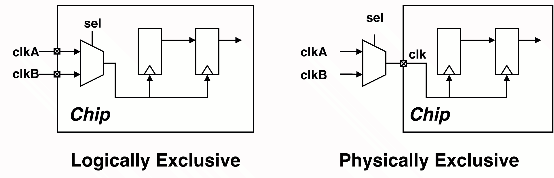
The set_clock_groups command tells the timing analyzer that certain clocks should not be analyzed against each other. There are two types of exclusivity:
Logically Exclusive: The clocks can physically propagate through the same path, but they are never active simultaneously during operation (e.g., controlled by a mux select signal or mode register).
1
2
3
set_clock_groups -logically_exclusive \
    -group clk_a_mux \
    -group clk_b_mux
Physically Exclusive: The clocks cannot physically coexist on the same path—they are defined on the same pin/port but represent mutually exclusive operating modes (e.g., multiple clocks defined on the same input port for different speed grades).
1
2
3
set_clock_groups -physically_exclusive \
    -group clk_a_mux \
    -group clk_b_mux
Is this blog helpful? Help fuel more in-depth technical content by treating me to a coffee! Your support keeps the knowledge flowing ☕✨
